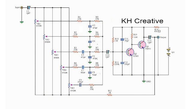
Transistor equalizer circuit diagram
We use it for controlling the audio frequency in some kinds of audio frequency responses that are not flat.
Which we cannot use a normal tone control circuit. Because it has a too wide bandwidth.
We need to use a good equalizer circuit that can respond to narrow bandwidth down. And, divide into frequency bands increased to 5 channels or more.
It can control specific actions required by frequency bands.
If you want to learn a basic equalizer. I am going to show you a simple circuit like the transistor tone control circuit.
Transistors Graphic equalizer circuit
This equalizer circuit can be adjusted the frequency to 5 channels 60 Hz, 100 Hz, 1 kHz, 3 kHz, and 12 kHz.
And, this project consists of stereos, right and left channels. It is the same. So, we will learn only the right channel (Mono).
In-circuit is Mono. If you want stereo. Just add Mono another one only.
I want you to understand easier. Seeing the block diagram may you more.
When we enter a signal to the input. Then, C1 passes a signal to coupling through pin1 each potentiometer (VR1-VR5).
If we adjust VR5 to a higher level in the middle of a potentiometer.
This signal will come to a high and low-frequency filter of each band. They include the R and C networks.
Next, the signal that through each band be combined together.
Then, C10-capacitor passes the signal to coupling to a base of Q1 and Q2.
Both transistors are common emitter amplifiers.
The higher signal goes out of a collector of Q1. It is out of phase with the input.
Then, the highest signal or the output signal comes out of the emitter of Q2 via C13.
And, some signals will be feedback through R12 to each leg 3 of the potentiometer (VR1 to VR5).
When we adjust them to this point. A feedback signal will refute with an input. So, this is a cut-off point.
How to builds this project
First, find the components of this project. See the parts lists below.
Parts you will need
0.25W Resistors, tolerance: 5%
- R1, R2, R3, R4: 22K
- R5, R6, R7, R8, R9: 33K
- R10: 1M
- R11: 220K
- R12: 1K
- R13: 5.6K
- R14: 470 ohms
- VR1-VR5: 100K(B) stereo potentiometer
Capacitors
- C1,C10,C13: 1uF 50V Electrolytic
- C2: 473 Mylar
- C3: 223 Mylar
- C5,C6: 472 Mylar
- C7, C8: 102 Mylar
- C9: 390pF Ceramic
- C11: 39pF Ceramic
- C12: 100pF Ceramic
Semiconductors
- Q1: A1013 Transistors
- Q2: C2383Transistors


Comments
Post a Comment